
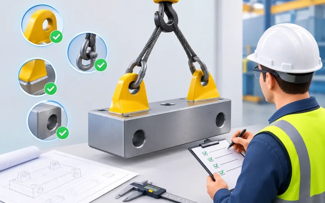
A lifting lug can look simple on a fabrication drawing: a plate, a hole, a weld, and a stated capacity. On the jobsite, lifting lug design carries much more responsibility. The lug must transfer the actual lifting forces into the structure without yielding, tearing, buckling, cracking, or creating an unstable pick. If it needs proof load certification before use, the design details and supporting records must be ready before the test is scheduled.
For contractors, fabricators, rigging crews, and equipment managers, the practical goal is straightforward: confirm that the lug is designed for the intended lift, built as designed, and tested under the required conditions. Missing any one of those steps can stop an inspection, delay a mobilization, or require rework after the equipment reaches the field.
Start With the Actual Load Case
The rated load marked on a lug is only useful when it matches the way the lug will be used. A 10,000-pound component does not automatically create a 10,000-pound force at each lifting point. The center of gravity, number of pick points, sling angle, unequal load sharing, and lift geometry can all change the force applied to each lug.
Start with the gross lifted weight. Include the item being lifted, permanently attached components, rigging that is carried by the lug, and any expected contents if the item will not be empty during the lift. Then establish the pick configuration. A two-leg bridle at an angle places a higher tension in each sling leg than a straight vertical pick. As the angle becomes flatter, the tension rises quickly.
Do not assume every lug shares the load equally. Real picks can have tolerances in lug elevation, sling length, center-of-gravity location, and structural stiffness. A qualified engineer should define the load distribution assumptions, especially for multi-point lifts, offset loads, rotating picks, or equipment that will be lifted repeatedly.
Dynamic effects also matter. A controlled shop lift has different demands than a field pick where a load may be accelerated, stopped, or affected by wind and crane movement. The intended service must be clear in the design basis.
Key Lifting Lug Design Checks
A proper lifting lug design is not just a plate-thickness calculation. The plate, hole, pin or shackle connection, welds, and supporting structure work together. The weak point controls the allowable capacity.
Lug Plate and Hole Geometry
The lug plate must have adequate material around the hole to resist bearing, shear-out, net-section tension, and bending. Hole size, edge distance, plate width, and thickness all affect these checks. A hole cut too close to the top or side edge can reduce capacity even when the plate itself appears heavy enough.
The hole must also suit the selected shackle, pin, or hook connection. Forcing an oversized pin through a hole, using a shackle that bears on the lug edge, or allowing side loading can introduce bending that was never included in the design. The connection should have enough clearance to articulate as the rigging aligns under load.
Plate shape matters as well. Sharp transitions, abrupt profile changes, and poorly finished thermal cuts can create stress concentrations. A smooth, well-detailed lug profile helps reduce localized stress and makes inspection easier.
Out-of-Plane Loading and Side Pull
Many field problems begin when a lug designed for in-plane loading is used with rigging that pulls sideways. A single plate lug is usually strongest when the force stays in the plate plane. Side loading can bend the plate, twist the supporting member, and change the stress at the weld.
If the lift requires a change in direction, consider the need for paired lugs, a padeye assembly, a spreader beam, or rigging hardware that maintains alignment. The right solution depends on the equipment geometry. What should not happen is treating a side pull as a minor field adjustment.
Weld Design and Supporting Structure
The weld is part of the lifting system, not an afterthought. Weld size, length, configuration, material compatibility, access for proper welding, and inspection requirements must match the calculated load path. A large lug welded to a thin wall or lightly reinforced frame does not create a high-capacity lifting point.
The structure behind the lug needs equal attention. Load can spread through a shell, beam flange, lifting frame, or reinforcement plate in ways that introduce local bending and distortion. In some cases, the lug plate is adequate but the supporting member is not. Reinforcement may be required to distribute the load into the main structure.
Fabrication quality must match the drawing. Verify the specified weld process, weld size, and any required visual, magnetic particle, ultrasonic, or other examination requirements. If the design calls for full-penetration welds, a field substitution should not be accepted without engineering review.
Material Traceability Is Part of Compliance
A lifting lug is only as traceable as its material and fabrication records. Plate grade, thickness, heat numbers, mill test reports, welding procedures, welder qualifications, and inspection records may be required by the project, owner, engineer, or inspector.
This is especially important when a lug is fabricated as part of a custom lifting frame, vessel, spreader, or structural assembly. If the material cannot be identified, proving that it meets the design assumptions becomes difficult. The same issue applies when an existing lug is modified, repaired, or relocated.
Keep the documentation with the equipment file, not just in a fabricator’s inbox. A clear record package saves time when an inspector asks how a lifting point was designed, what material was used, and whether it was tested.
Design Standards and Project Requirements
The applicable design criteria depend on the equipment type, intended use, customer specifications, and governing regulations. Common industry references may include ASME standards for below-the-hook lifting devices, project engineering specifications, or owner requirements. The correct standard is not something to guess from a nameplate.
A lifting lug on a one-time construction assembly may have different requirements from a production lifting beam, marine fixture, or recurring maintenance tool. Capacity marking, design factors, inspection intervals, proof test levels, and documentation requirements can vary. Confirm the governing requirement before fabrication starts or before scheduling a test.
Where an engineer has provided stamped calculations or drawings, treat them as the controlling design record. Any changes to plate thickness, hole size, lug location, weld detail, rigging arrangement, or rated capacity should be reviewed before the equipment is placed into service.
Prepare for Proof Load Testing
Proof load testing verifies performance under a controlled test load, but it does not replace sound engineering or fabrication control. A successful test does not correct an undocumented material substitution, an unapproved weld repair, or use outside the intended load direction.
Before testing, have the equipment identification, rated capacity, load-test requirement, drawings or calculations, and fabrication records available. Inspect the lug for visible cracks, deformation, excessive corrosion, unauthorized modifications, damaged holes, or questionable welds. Confirm that the test setup will load the lug in a way that represents its intended service.
The test fixture and attachment hardware also need to be suitable. A test can be invalid or unsafe if shackles are undersized, loaded incorrectly, or positioned to introduce side loading. Make sure there is adequate clearance around the lug and that personnel are kept clear during loading.
After the test, the certificate should clearly identify the equipment, test date, applied load, result, and any limitations or observations. That documentation is what a project team can present when an inspector asks whether the lifting point is approved for use.
Common Issues That Create Delays
The fastest way to lose time is to schedule testing before the lifting plan and documentation are settled. Common issues include a lug with no marked capacity, a mismatch between the drawing and the fabricated part, no material records, insufficient hole clearance for the intended shackle, or a proposed test setup that pulls the lug in a different direction than service.
Another common problem is designing around a vertical load, then using low-angle sling legs in the field. The lug may be physically intact, but the applied tension can exceed the assumed design load. Address the actual rigging arrangement early, particularly when crane access or headroom forces flatter sling angles.
For equipment already in the field, photograph the lug, measure the plate and hole dimensions, identify the intended rigging hardware, and gather any available drawings before requesting certification. That gives the testing provider and project team a clear starting point and reduces last-minute surprises.
When a lifting point is needed for a live project, Pacific Load Testing can support on-site proof load testing and certification planning in the San Diego area. Bring the design records, the actual lift configuration, and the required inspection criteria to the table early. A lifting lug that is designed, fabricated, and documented correctly gives the crew one less reason to stop work when the inspector arrives.